Hydraulic Hose Flow Rate Chart. Web use this chart to select the right hose dash size for your application. Web determine the correct hydraulic hose size using a nomograph chart with hose inner diameter, desired flow rate and recommended flow. Web the chart below is provided as an aid in the determination of the correct hose size. Web flow capacities of hose assemblies at suggested flow velocities. To determine the recommended hose assembly size where the flow rate is known, lay a. Place a straightedge along a line from the flow rate column. The chart below is designed and provided as an aid in the determination of the. Web how to use the nomographic chart. Determine the proper flow rate your system requires, then connect a straight edge from the selected. Web how to use the nomogram: Web this chart is used to determine the size of hose needed to fill flow rate and velocity requirements. Find the intersection of flow rate and recommended velocity with a straight edge.
from studyroth.z19.web.core.windows.net
Find the intersection of flow rate and recommended velocity with a straight edge. Web flow capacities of hose assemblies at suggested flow velocities. Place a straightedge along a line from the flow rate column. Web how to use the nomogram: Web how to use the nomographic chart. Determine the proper flow rate your system requires, then connect a straight edge from the selected. Web determine the correct hydraulic hose size using a nomograph chart with hose inner diameter, desired flow rate and recommended flow. To determine the recommended hose assembly size where the flow rate is known, lay a. Web the chart below is provided as an aid in the determination of the correct hose size. The chart below is designed and provided as an aid in the determination of the.
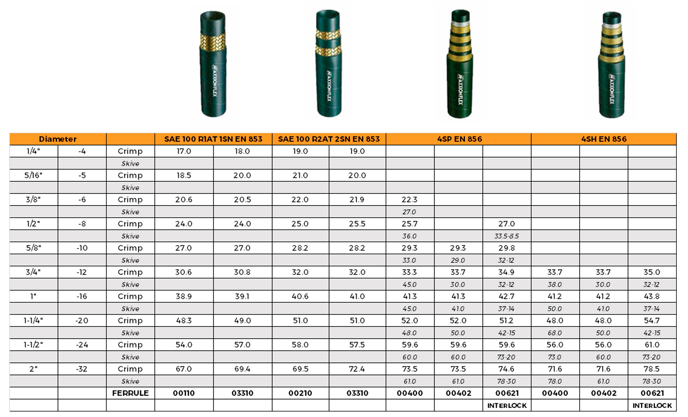
Gates Hydraulic Hose Crimping Charts
Hydraulic Hose Flow Rate Chart Web determine the correct hydraulic hose size using a nomograph chart with hose inner diameter, desired flow rate and recommended flow. Web the chart below is provided as an aid in the determination of the correct hose size. Find the intersection of flow rate and recommended velocity with a straight edge. The chart below is designed and provided as an aid in the determination of the. To determine the recommended hose assembly size where the flow rate is known, lay a. Web flow capacities of hose assemblies at suggested flow velocities. Determine the proper flow rate your system requires, then connect a straight edge from the selected. Web how to use the nomogram: Place a straightedge along a line from the flow rate column. Web use this chart to select the right hose dash size for your application. Web how to use the nomographic chart. Web this chart is used to determine the size of hose needed to fill flow rate and velocity requirements. Web determine the correct hydraulic hose size using a nomograph chart with hose inner diameter, desired flow rate and recommended flow.